This series of filters adopts the Fuller technology, namely, 0.3-0.61MP compressed pulse air is injected in each filter bag of one chamber, with the coordination of off-line switch valve, to shake off soot and dust on the surface. 2-2.5m filter bags are used in this series of filters.
I.OperatingPrinciple
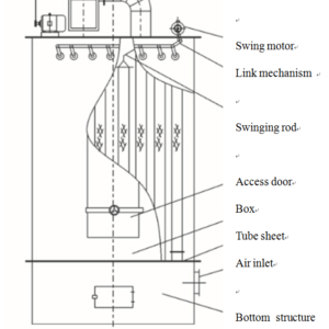
The filtration mechanism of the bag filter is a result of combined effects, including gravity, inertia force, collision, electrostatic adsorption, screening effect, etc. When gas containing soot and dust enters into the filter through an inlet, larger dust particles directly fall because of the increase of its cross-sectional area and decrease of wind speed, but smaller soot and dust particles stay on the surface of the filter bag. The purified gas passing through the filter bag is discharged from the induced draft fan via an outlet. Along with continuous filtration, soot and dust on the surface of the filter bag are gathered, and the resistance of the filter bag increases ceaselessly. When the equipment resistance reaches a certain limit, the accumulated soot and dust on the surface of the filter bag should be eliminated in time. Under the action of external forces (mainly including pulse compressed air, blowback gas, mechanical vibration, etc.), after vibrating and blowing back the filter bag, soot and dust attached to the surface of the filter bag is eliminated, so that the filter bag can be recycled, realizing continuous filtration, to ensure continuous and stable operation of the equipment.
II. Characteristics
- The equipment adopts the large pulse valve for deashing, with good deashing ability, good effect and long service life.
- The equipment is applicable to control of high-concentration soot and dust.
- The equipment has a compact structure and covers a small area, to save investment in capital construction.
- The equipment has a few of deashing fittings, with low failure rate and less maintenance fee.
III. Selection of the Filter
- Selection of filtration velocity:Filtration velocity refers to wind speed (m/min) passing through filter material, also known as air cloth ratio. When selecting filtration velocity, various factors should be taken into account, including the characteristics of filtering medium, temperature, humidity, dust concentration, deashing mode, properties of filter material, etc. Filtration velocity not only decides the size of the filter, but has a great influence on the resistance of passing through filter material, dedusting efficiency, deashing efficiency, etc. In general, the value range of filtration velocity of the bag filter is 0.5 to 2.5m/min.
- The calculation of filtering area is based on the following formula:
An=Q/60Vn(m2)
In the formula, An means net filter area (m2)
Q means air volume, also called volume of flue gas to be treated (m3/h)
Vn means net filtration velocity (m/min) - Selection of operating temperature and filter material:Operating temperature of the filter directly affects the selection of filter material: different temperatures at the inlet of the filter result in the selection of different filter materials.
IV. Installation and Debugging
- For convenience of transportation, the equipment is disassembled before delivery (the structural parts are only coated with anti-rust paint, but is painted with finished coast on the spot). After receiving the equipment, first of all, check whether the parts are missing according to the equipment list, and then check whether they are damaged in transit. Any damage incurred in transit should be promptly repaired, and the incoming equipment should be kept, to prevent damage, pilferage, etc.
- Ash discharging device should be specially inspected. The rotating or sliding parts are coated with lubricating grease, and lubricating grease is also injected into the reduction gearbox, so that the parts can run normally.
- The installation of the filter should be carried out according to equipment drawings, relevant national and industrial installation specifications.
- The equipment is installed from bottom to top. The equipment foundation must be consistent with the design drawings, and be checked and overhauled before installation. The support is hoisted, after adjusting the levelness and verticality, cross beam and ash hopper are installed. After fixing the hopper, check related dimensions. After error correcting, the lower box, the middle box, the upper box and air duct are hoisted respectively, and then air bag, pulse valve, injection pipe, electrical system and compressed air pipeline system are installed.
- Installation of injection pipe should strictly accord with the drawings, to ensure there is a certain distance between the tube sheet and it, the center of nozzles on the injection pipe is in line with that of the tube sheet hole, with the deviation of less than 2 mm.
- All access doors and connecting flange shall be equipped with sealing gaskets. The sealing gaskets of access door should be bonded with the adhesive. The junction of sealing gaskets is mitered or spliced, without any gap, to avoid air leakage.
- When installing a compressed air pipe, dirt in the pipe should be blown away to avoid blocking. After installation, the pressure of the pipe will be tested, and the test pressure is 1.15 times as working pressure. When pressure testing, the safety valve should be closed. After pressure testing, the pressure reducing valve will be adjusted to the regulated pressure.
- Power supply and control circuit are installed according to the installation diagram and instructions of the electrical controller.
- After completing the complete installation, the filter should be re-checked and maintained according to the drawings. Welded joint inside and outside the box, air duct and ash hopper should be strictly inspected, especially, airtight welded joint. Once defects such as welding leakage, air hole and seaming are found, repair welding should be conducted, to ensure its intensity and airtightness. When necessary, kerosene leakage detection should be conducted, and compressed air is used for pressurizing the filter, to detect the leakage.
- When there is a demand for pressurizing, the pressure test is conducted for the filter as required. In general, test pressure means that negative pressure of the fresh air chamber is multiplied by the coefficient of 1.15 according to the requirement, and the minimum pressure is wind pressure value of the system fan in the rear of the filter. After 1h pressure maintaining, the leakage rate should be less than 2%.
- The last procedure is to install the filter bag and paint finished coat. The filter bag is installed after removing the injection pipe. When handling and parking the filter bag, please note any contact and collision of the bags with the surrounding hard objects and sharp-angled objects should be avoided. It is prohibited to stamp and press the bags, to avoid breakage. The filter bag mouth should be tightly embedded in the tube sheet hole, without any inclination and gap. The bag frame (keel) should be vertical and be placed down from the bag mouth.
- Single machine debugging is performed after installation (pressure test) of the filter. All kinds of valves, including air release valve, discharge valve, spiral conveyor and so on, are debugged manually, and then are driven electrically. All mechanical parts should have no looseness and no locking, but good flexibility and airtightness. And then the equipment implements 8h no-load test run.
- The test of no-load simulation is conducted for the PLC. At first, check whether pulse valve, exhaust valve, discharge valve and the line of spiral conveyor are unobstructed, check whether valves are opened and closed normally. Deashing in each chamber is conducted according to timing control and procedures of electric control. Timing should be accurate, the movement of each component be correct, and the controlled valve be opened and closed as requested.
- Linkage debugging: Under the conditions of starting up the dust removal system and running the system fan, load linkage is implemented. The equipment runs by repeating Clause 13.
- Load run: The processing equipment operates formally, and the filter formally removes dust by filtration. In addition, the PLC also puts into operation (usually 5-10 minutes beforehand), checking all the moving parts and valves at any time, recording the operating parameters. According to timing control, when the resistance of the filter reaches the specified resistance value (e.g., 800-1500Pa), the PLC is manually opened for ash removal of the filter bag, and will halt after deashing in each chamber is completed. Then, count up the time when the resistance reaches the specified value, manually open the PLC for ash removal of the filter bag, which will be repeated for many times. After the stable interval time is obtained during the secondary deashing cycle, the time data can be considered as the radix of “timing” control of the PLC, and will be input in the PLC. After that, the PLC can automatically execute “timing control” and officially put into operation.
V. Maintenance and Overhaul
- The filter should be operated and maintained by a specially-assigned person, comprehensively grasping the performance and structure of the filter, finding and solving the problem in time, to ensure the dust removal system can normally run. Operators on duty should record the running conditions on duty and relevant data.
- Rotating parts should be smeared with lubricating grease on a regular basis.
- When soot and ash are found to discharge from the outlet, it indicates that a filter bag has been broken. When maintenance, blow out and open the upper cover. If the bag mouth is found to have ash deposition, it shows the filter bag has been broken, and it should be replaced or repaired..
- In general, the resistance value of the filter is 800-1500Pa, and the maximum one is 1800Pa. The deashing cycle is adjusted by the set switch in the control cabinet according to the actual resistance.
- The air filter of the compressed air system should discharge pollutants regularly, and the drain valve at the lowest point of the gas bag should drain water regularly. In addition, the filter with an air storage tank also should drain water regularly.
- The control valve should be overhauled by professionals, the electromagnetic valve and pulse valve should be inspected at fixed period.
There are no reviews yet.